In this post, the goal was to solder a good connection between each of the four motors and the electronic speed controller. The motors I picked were the Racerstar 2205-2300KV motors, since they are quite cheap and deliver really good performance for the money. The ESC I picked was a 4 in 1 20A ESC, also from Racerstar, in order to save space. However, I did have some troubles with this ESC, as you will see in my description below the video.
Even though this was not my first time soldering, the job I did of soldering was so poor it admittedly may have as well been my first time soldering. As you can see in the photo below, the first motor I hooked up had major inconsistencies in my soldering and I kept forgetting to put the heat shrink on before soldering, so I would solder two of the cables together and then realize that I had forgotten to add a little bit of heat shrink, and sometimes when I would remember I would cut a little bit too much of heat shrink, as you can see in that photo below.
As you can see in the photo above, even though soldering two cables should not take up that much space, I managed to cut a huge strip of heat shrink, which was clearly way more than I needed. In addition, I didn't cut and strip enough of the cable, so in the future the propellers may cut into the cables. In the photo below, I had some cable crossover and the cable had some soldering issues, since they did not twist together as nicely as I would have liked.
Even though my soldering skills are quite poor, I do use a multimeter to check for continuity between my connections and I do check to make sure that they connect to the right place - so far so good. One of the things about this ESC that I picked is the order of the motors compared to the software I used: Betaflight. As in the diagram below, their motors are arranged as follows:
However, below is a picture of how I soldered it up:
As you can see on the right side, my motors have crossed over. Here's the explanation: on the ESC, motor 1 being on the top left as I've flipped the quadcopter upside down relative to the camera position, you can see that while motors 1 and 2 are wired up to the motors closest to them, motor 3 on the ESC is actually where motor 4 is located, giving me two options. What I've done here is decide to simply have the wires cross over, although I could have switched the data cables and wired motor 3 to motor 4 on the flight controller (not pictured) and motor 4 to motor 3. Had I done that, the build would have looked far cleaner, but as this is my first build, I'm more about the learning experience and getting the drone to work for the first time: that would make me excited enough. In the future that could be a future goal, although building a hexacopter also seems quite fun in terms of trying to build a drone that can go as fast as possible.
I have several more pictures, but as they don't flow together and are unnecessary to knowing how I built this drone, I've decided to not build them. Have a nice day!
Even though this was not my first time soldering, the job I did of soldering was so poor it admittedly may have as well been my first time soldering. As you can see in the photo below, the first motor I hooked up had major inconsistencies in my soldering and I kept forgetting to put the heat shrink on before soldering, so I would solder two of the cables together and then realize that I had forgotten to add a little bit of heat shrink, and sometimes when I would remember I would cut a little bit too much of heat shrink, as you can see in that photo below.
 |
| Really showing here how bad my soldering can get. |
As you can see in the photo above, even though soldering two cables should not take up that much space, I managed to cut a huge strip of heat shrink, which was clearly way more than I needed. In addition, I didn't cut and strip enough of the cable, so in the future the propellers may cut into the cables. In the photo below, I had some cable crossover and the cable had some soldering issues, since they did not twist together as nicely as I would have liked.
 |
| The poor job of soldering I can do. |
Even though my soldering skills are quite poor, I do use a multimeter to check for continuity between my connections and I do check to make sure that they connect to the right place - so far so good. One of the things about this ESC that I picked is the order of the motors compared to the software I used: Betaflight. As in the diagram below, their motors are arranged as follows:
 |
| Betaflight motor configuration. Source: propwashed.com |
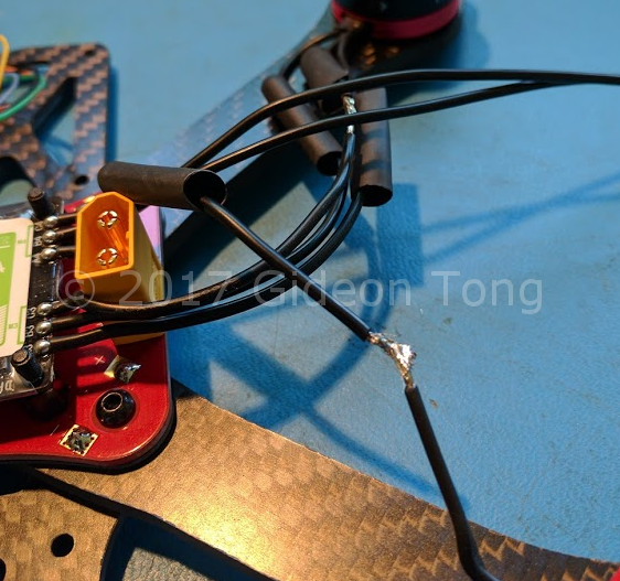
However, below is a picture of how I soldered it up:
 |
| Configuration of how I wired up the ESC. |
As you can see on the right side, my motors have crossed over. Here's the explanation: on the ESC, motor 1 being on the top left as I've flipped the quadcopter upside down relative to the camera position, you can see that while motors 1 and 2 are wired up to the motors closest to them, motor 3 on the ESC is actually where motor 4 is located, giving me two options. What I've done here is decide to simply have the wires cross over, although I could have switched the data cables and wired motor 3 to motor 4 on the flight controller (not pictured) and motor 4 to motor 3. Had I done that, the build would have looked far cleaner, but as this is my first build, I'm more about the learning experience and getting the drone to work for the first time: that would make me excited enough. In the future that could be a future goal, although building a hexacopter also seems quite fun in terms of trying to build a drone that can go as fast as possible.
I have several more pictures, but as they don't flow together and are unnecessary to knowing how I built this drone, I've decided to not build them. Have a nice day!
Comments
Post a Comment
Hey! Keep the comments section cordial please, thanks!